
This Installation Guideline provides a step-by-step guide intended for use by Contractors planning to construct Tensar reinforced soil structures with Envirocon Interbloc precast elements. Any drawings or photographs are typical only and the contractor should satisfy themselves that the techniques discussed and shown are suitable for the specific conditions they are working under. The geometry of the blocks may vary as can be seen from the photographs above, therefore the following construction sequence is indicative only. This document should be read in conjunction with the specification and drawings for each individual contract.
Foundations and Footings
- The formation level should be prepared in accordance with requirements of the contract.
- Evaluation and suitability of the bearing capacity of the foundation soils is the responsibility of the Engineer and should be commensurate with the requirements of the design brief.
Transportation and Handling of the Blocks:
- Blocks should be transported with cast-in Tensar geogrid tags facing out. Where blocks with geogrid tags are being placed next to each other the distance between the blocks should not be less than 100mm. Care must be taken to prevent damage to the Tensar geogrid tabs when handling the blocks.
- Off-loaded blocks should be inspected and any block found to be defective, e.g. cracked or broken corners, damaged geogrid tabs, stains on exposed face, cracks in panel surface etc. should be set aside for further inspection by the Engineer to determine their suitability as to repair, incorporation into the works, or rejection.
- Refer to Envirocon’s article on lifting the blocks for further generic information on handling and storing Interbloc blocks.
Handling of Geogrid
- Geosynthetic reinforcement must be stored in covered building with zero exposure to UV radiation, chemicals, open flames, welding sparks, precipitation and standing water
- Stacking of geosynthetic reinforcement must be limited to 3 rolls height
- Geosynthetic reinforcement rolls must not be dragged during handling at all stage
Installation of Blocks and Filling:
- The blocks should be carefully lifted into position using the appropriate lifting equipment.
- Longitudinal vertical alignment should be checked and adjusted by using shims.
- Subsequent blocks should be carefully placed and aligned using a string line as a guide.
- Once the blocks have been positioned, the placement of the reinforced fill may commence.
- Place and compact approved fill as specified in the contract documents, up to the level of the first layer of Tensar geogrid. With the important restriction within 2m of the face block to use only a vibrating plate compactor or vibrating roller with a mass per metre width less than 1300kg and a total mass less than 1000kg.
- Tensar uniaxial geogrid is supplied in rolls, 1.3m wide x 50m or 75m length, unwrapped and bound using coloured identifying tape. The material is UV protected and may be stored outside until use.
- Tensar HDPE bodkins are supplied in cardboard boxes of 40No. These may be stored outside until use but may benefit from being stored undercover to prevent water damage to the cardboard box.
- Cut the Tensar geogrid from the roll to the required design length and place into position.
- Tensar geogrid should be installed to the levels, lengths and orientations as shown on the drawings issued for construction.
- Using the correct Tensar bodkin[1] to connect the Tensar geogrid reinforcement to the cast-in Tensar geogrid tab as per the detail in Figure 3.
- To tighten the bodkin joint, insert the tensioning beam[2] through the Figure 3 apertures at the free end of the Tensar geogrid and apply a load sufficient to remove any slack in the bodkin joint. Leverage on a steel bar dug into the fill through the loop on the beam is usually sufficient.
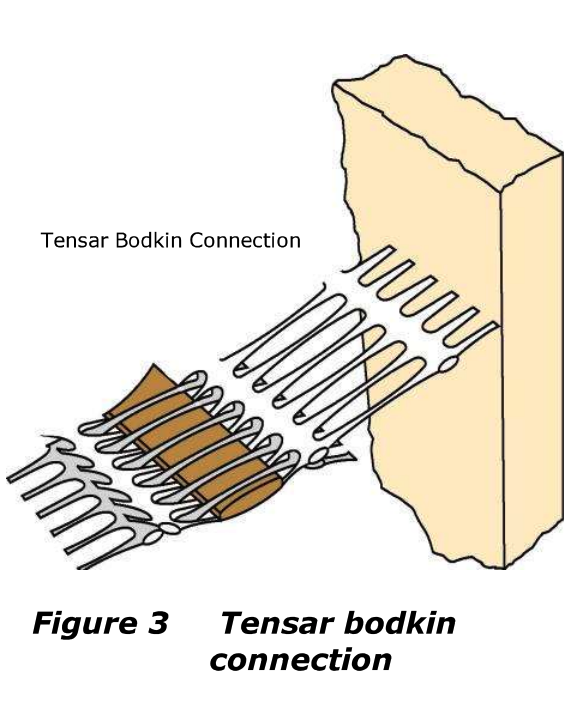
Tensar Bodkin connection
- Whilst maintaining tension, place a layer of fill on the Tensar geogrid that is sufficient to restrain it in position when the load is released.
- Release the tension and remove the beam. Do not allow construction plant to travel on the Tensar geogrid until it is covered by at least 150mm of fill.
- Repeat procedure for as many adjacent blocks as is appropriate.
- Repeat step 17 compacting fill in the appropriate Iayer thickness’ up to the level of the next layer of Tensar geogrid.
- Continue construction up to the full height of the structure.