
1. Case description
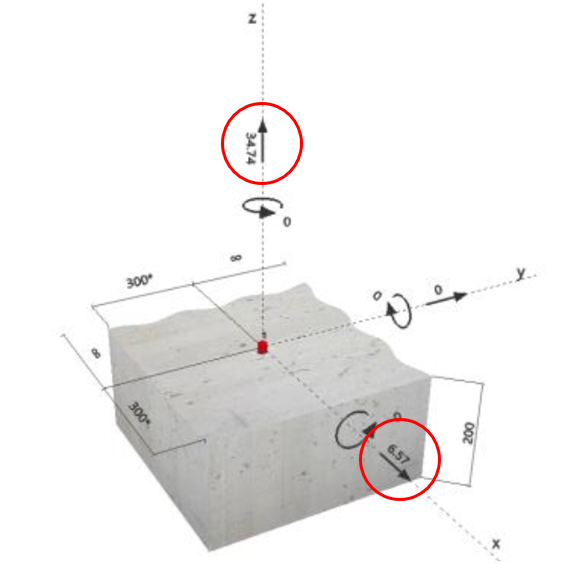
A retaining wall with dimensions as shown in Figure 1 is adopted for this document. The wall is constructed from Interbloc modular concrete blocks, which rests over an engineered foundation. The wall is also reinforced vertically with ∅ 16 rebars to provide extra resistance against overturning moments.
|
|
|
Figure 1. Geometry of the considered wall |

A list of the required parameters for the design is shown in Table 1.

2. Code compliance
The design procedure in this document is based on the guidelines of the NZ building code clause B1/VM4 and the earthquake geotechnical engineering practice module 6.
3. Actions
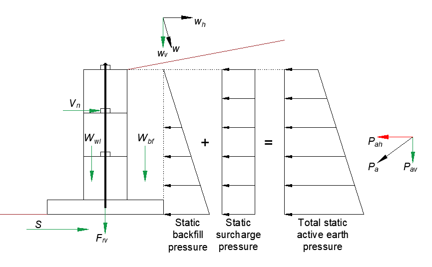
The de-stabilizing and stabilizing actions in the static and earthquake cases are illustrated in Figure 2 and 3.
|
|
|
Figure 2. Actions in the static case. De-stabilizing forces in red and stabilizing forces in green |
|
|
|
Figure 3. Actions in the earthquake case. De-stabilizing forces in red and stabilizing forces in green |

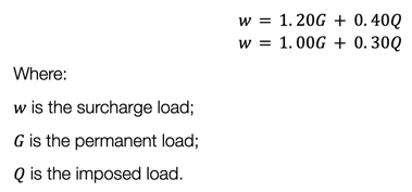
Before calculating the de-stabilizing and stabilizing forces, the below load combinations are used to calculate the surcharge load in the static and earthquake cases respectively.
3.1. De-stabilizing forces in the static case
The destabilizing forces in the static case are only caused by the horizontal component of the total static active earth pressure. The horizontal component of the total static active earth pressure is calculated as shown below. 
The total static active earth pressure is calculated as shown below.
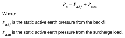
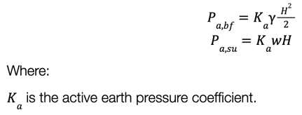
The backfill and surcharge load static active earth pressure components are calculated as shown below.
3.2. Stabilising forces in the static case
3.2.1. Vertical component of the total static active earth pressure
The vertical component of the total static active earth pressure can be calculated as shown below.
3.2.2. Vertical component of the surcharge load
If a permanent source of load is constructed behind the wall, a footpath for example, and it is line of action extends above the cantilever part of the wall foundation, the vertical component of the surcharge load can be considered as a stabilising force. The surcharge load is calculated following a different load combination in this case as shown below.
![]() The vertical component of the surcharge load for the geometry shown in Figure 1 can be calculated as shown below.
The vertical component of the surcharge load for the geometry shown in Figure 1 can be calculated as shown below.
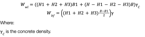
3.2.3. Self-weight components
The self-weight components for the geometry shown in Figure 1 can be calculated as shown below.
3.2.4. Lateral resistance provided by the shear key
If the wall is not vertically reinforced, the lateral forces between block layers are mainly resisted by the shear keys. The capacity of the shear key can be calculated based on NZS 3101: Part 1: 2006. Section 7.5 “Shear strength of members” as shown below.

The Interbloc shear key runs across the entire length of the block unit and has an area of 14000 mm2/m length.
3.2.5. Resistance from the unbonded vertical reinforcements
The unbonded vertical reinforcements enhance the overall stability of the wall against overturning moments and lateral shear action between block layers by applying vertical pressure at the top of the wall. The reinforcements are anchored to the foundation using chemical mortars. Hilti HIT-RE 500V3 or HIT-HY 200-R are recommended for this application. The verification of the selected rebar diameter and anchorage depth can be carried out using Hilti Profis Anchor software.
The input forces to Hilti Profis Anchor software are the horizontal component of the static active earth pressure and the tensile force cause by the overturning moment of that force. The tensile force can be calculated by dividing the overturning moment over half a block width. As an extra precaution, the lateral resistance from the friction force between the block units and the foundation can be neglected. An example showing the input forces to Hilti Profis Anchor software is shown in Figure 4.
|
|
|
Figure 4. An example of inputting force to Hilti Profis Ancho software |
3.2.6. Resistance from the subsoil
The sliding resistance from the subsoil can be calculated based on the guidelines of clause B1/VM4 and practice module 6. The resistance must be calculated depending on the required ULS check.
For the short-term sliding ULS check, the sliding resistance is calculated based on the undrained shear capacity of the subsoil as shown below.
![]()

For the long-term sliding ULS check, the sliding resistance is calculated based on the angle of friction of the subsoil as shown below.

It is important to note that a factor of 0.67 must be applied to the value of ∅'to account for the smooth precast surface if the wall is not constructed over a cast-in-situ engineered foundation.
3.3. De-stabilizing forces in the earthquake case
The destabilizing force from the horizontal component of the total earthquake active earth pressure can be calculated as shown for the static case using the load combination shown in Equation (2). However, it is important to note that de-stabilizing safety factors shown in the guidelines of clause B1/VM4 and practice module 6 are set to unity in the earthquake case.
The inertial forces caused by the self-weight of the wall, the foundation and the backfill above the cantilever foundation can be calculated based on the guidelines of module 6, module 1, and the NZS 1170.0.
3.4. Stabilizing forces in the earthquake case
The stabilizing forces in the earthquake case can be calculated as shown earlier for the static case keeping in mind that all the stabilizing safety factors shown in the guidelines of clause B1/VM4 and practice module 6 are set to unity in the earthquake case.
4. Verifications
The following ULS checks are required based on the guidelines of clause B1/VM4 and module 6:
- Short-term bearing capacity of the subsoil beneath the wall’s foundation in the static case;
- Short-term bearing capacity of the subsoil beneath the wall’s foundation in the earthquake case;
- Long-term bearing capacity of the subsoil beneath the wall’s foundation;
- Short-term sliding of the wall’s foundation in the static case;
- Short-term sliding of the wall’s foundation in the earthquake case;
- Long-term sliding of the wall’s foundation.
The reader can refer to the guidelines of these codes to perform the above listed ULS checks.
Version 1 April 2023_Technical Support Manager