
1. What is the MSE wall system?
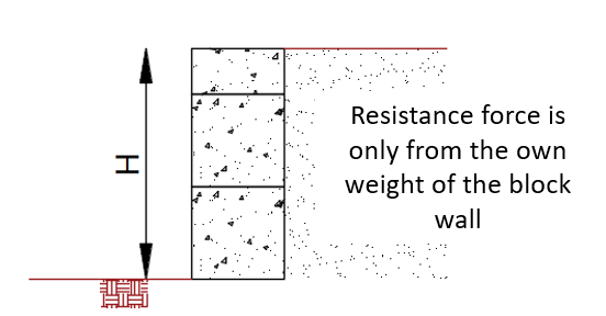
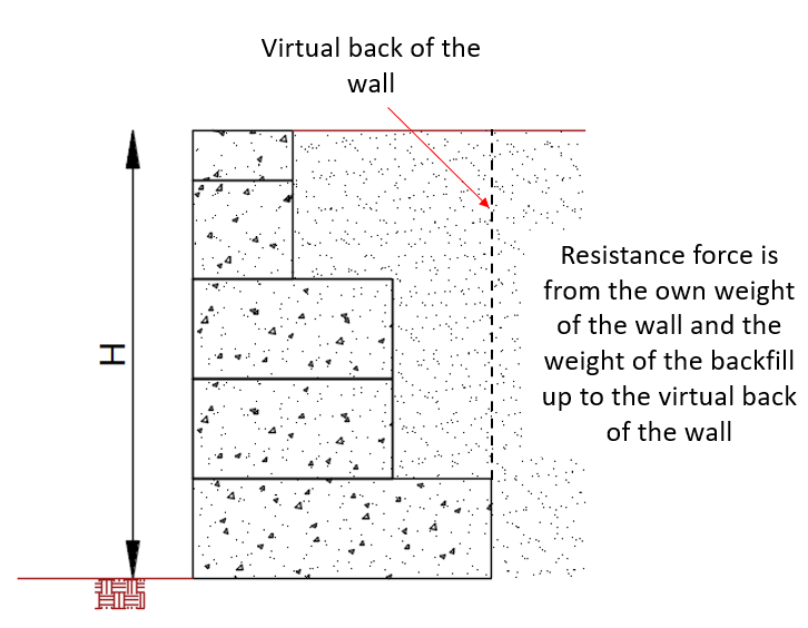
Mechanically stabilised earth (MSE) wall systems are a type of gravity retaining wall, which can be utilised in applications where the retaining height exceeds 2.4 m. It is also an option for lower retaining heights where the imposed surcharge load exceeds 12 kPa, or if there are sources of permanent loads creating excessive lateral pressure on the wall. The system utilises the self-weight of the backfill using geosynthetic grids as illustrated in Figure 1 (c).
|
|
|
|
|
|
|
|
|
|
|
Figure 1. Different types of gravity retaining walls including MSE walls |
|

2. How is the geogrid system integrated in Envirocon’s modular block system?
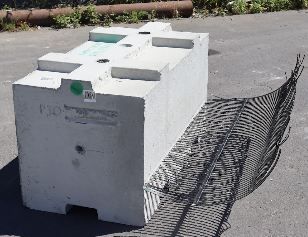
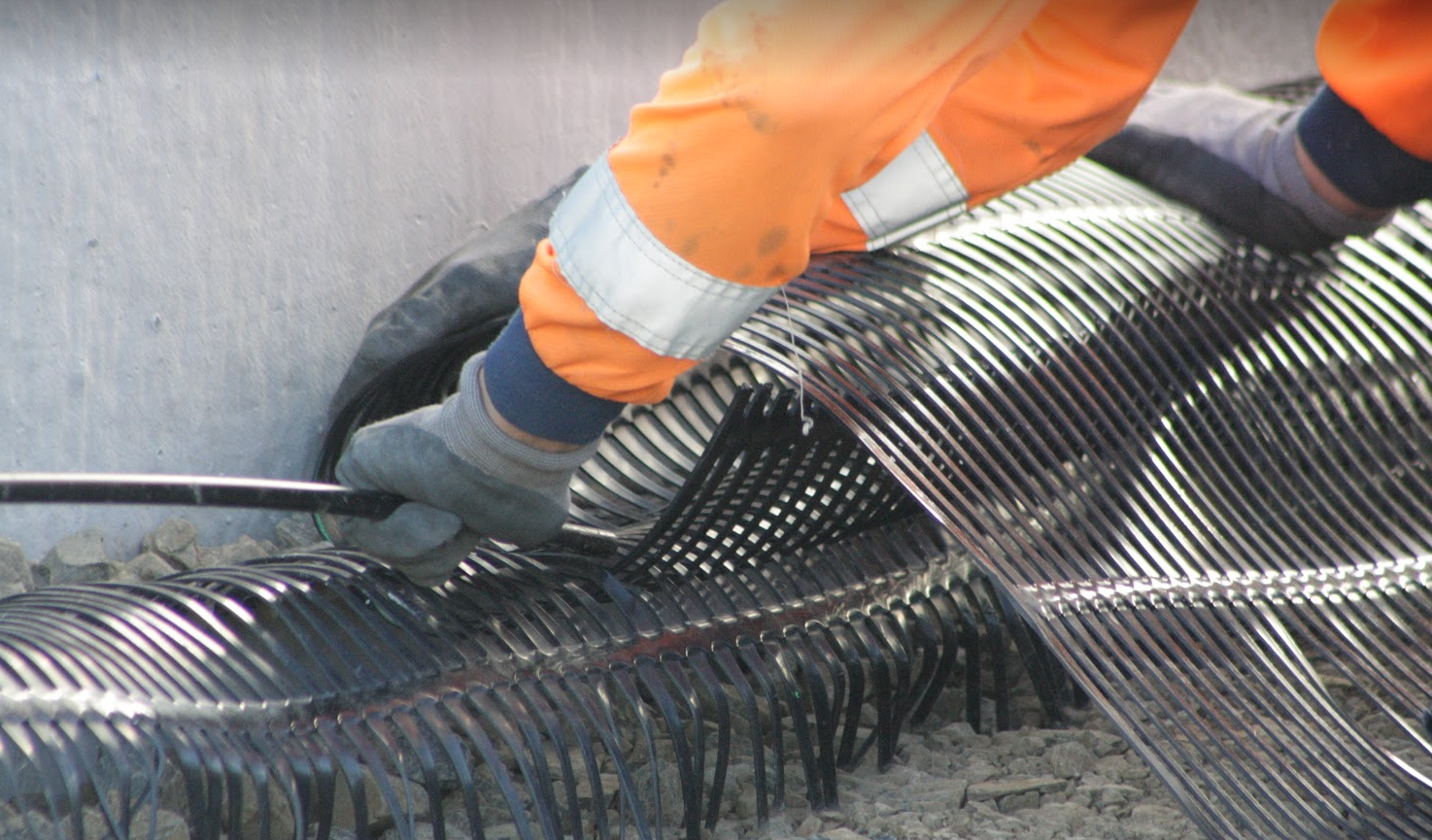
The geogrid is fixed inside the block mould before pouring concrete. The final product is a modular block with a short geogrid projecting from its back. The required extra length of the geogrid is then woven to the projected short length at the construction site using a bodkin. The whole process is illustrated in Figure 2.
|
|
|
| A modular block with cast-in geogrid | Attaching the extra length of geogrid to the projected short length |
|
|
|
|
Fully extended geogrids from the back of the wall |
|
|
Figure 2. Installation of the geogrid with Envirocon’s modular block system |
|

Once the geogrid is fully extended behind the wall, the backfill is placed in layers at the top and compacted based on the site requirements.
3. Design of MSE walls
There is no building code or standard to refer to for the design of MSE walls in New Zealand. However, it is possible to refer to the guidelines of the Transfund New Zealand Research Report No.239: Guidelines for Design & Construction of Geosynthetic-Reinforced Soil Structures in New Zealand. Based on this document, the following ultimate limit state checks are required for the design of MSE wall systems.
3.1 Static and seismic design external stability checks
The following checks are performed to confirm the external stability of the wall in the static case:
- Forward sliding: the resistance to sliding along the foundation soil and the reinforced backfill is confirmed against the total active earth pressure.
- Bearing capacity: the bearing capacity of the foundation soil to withstand the total weight of the MSE wall system is verified. This check can be performed according to the guidelines of B1/VM4.
- Overturning: the ability of the MSE wall system to remain stable is confirmed against overturning moments from the total active earth pressure.
3.2 Static and seismic design internal stability checks
The following checks are performed to confirm the internal stability of the wall in the static case:
- Tensile strength of the geogrid: the tensile strength of the geogrid is confirmed against the tensile forces at each geogrid layer.
- Pullout: the soil reinforcement interaction strength for pullout is confirmed against the tensile forces at each geogrid layer.
- Internal sliding: the potential for internal sliding is confirmed against the lateral earth pressure at each geogrid level.
3.3 Other design documents and commercial software
It is also possible to refer to other international document for the design of MSE wall systems. Design standards like the Australian standard AS 4678. However, it is important to note that this standard provides no guidelines for seismic design. Commercial software like the TensarSoil software can also be used.