There are eight influences on the design of a retaining wall structure as illustrated in the diagram;

- Height of the wall
- Slope of backfill
- The location of underground utilities
- Surcharges on the wall
- Parameters of backfill
- Parameters of underlying ground
- The profile of the wall
- Fall protection
- Earthquake
Height of the Wall
The higher the walls, the greater the pressure on the wall. A common question asked by customers is how high Envirocon can build walls. The height of the wall, along with the parameters, determine the type of wall built.
The table below provides an indicative maximum retaining height by product and wall type
|
Gravity |
MSE |
Cantilever |
|
|
Interbloc |
2.4m |
8.4m |
3.2m |
|
Stonebloc |
2.0m |
NA |
NA |
Slope of Backfill
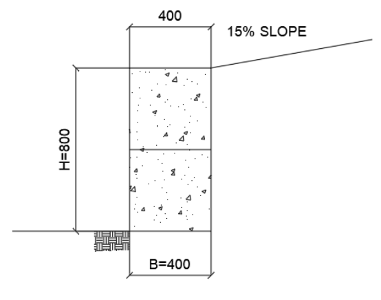
The higher the slope of the backfill extending from the top of the wall, the move load will be exerted on the wall. Higher slopes have a disproportionately higher load on the wall.
The slope behind the wall affects the overall stability of the wall. The slope behind the wall should be specified by an Engineer prior to the commencement of the design process.
Slope can be specified in percentages, degrees or gradients.
e.g.
- Gradient - 1:4
- Percentage - 25%
- Degrees - ~14°
These can be easily converted using online tools such as https://www.archtoolbox.com/calculating-slope/
Underground Utilities
Where a wall is to be built close to underground pipes there may be extra design requirements which may need to be met. This is referred to as bridging designs.
Standards related to underground services are governed by 55 territorial authorities and a myriad of water service providers, local lines companies, and gas distributors. As such standards and requirements are different in your local area. The following is based on Auckland and National standards and is intended to provide a general guide only.
Bridging, in a technical sense, is required when a retaining wall is within a defined ‘Zone of Influence’ in relation to an underground pipe. The assumption is that the retaining will exert pressure on the pipe and may damage it. Therefore a ‘bridging’ design is required to ensure the force of the wall is directed to a point outside the Zone of Influence.
There are two core scenarios where bridging may need to be considered:

The Zone of Influence is a wedge of area emanating from the pipe. The exact parameters of the zone will be specified by the local authority, however in Auckland it equates to 3V, or 45 degrees from the pipe.
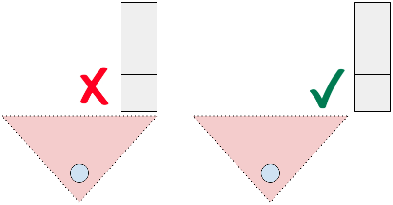
The calculation for this is the horizontal distance of the wall from the pipe divided by the depth of the pipe. Where the answer is less than 3, the wall is within the zone of influence.
Generally a structural engineer should be involved in specifying the solution, of which there are two;
- Bridging design - essentially this means spreading the load of the wall over an area of land to reduce the load on the pipe. This can be a very expensive exercise.
- Design exemption - segmental retaining walls, which both Interbloc and Stonebloc gravity walls are, may be exempted from requiring a bridging design in some cases on the basis the structure can be dismantled in the event of the need to access the pipe. This is provided by the consenting authority at the point of a consent review.
It is important to consider the possibility of bridging requirements at an early stage of the process to avoid technical difficulties later in the process. Bridging designs (if required) can be easily obtained from the projects Structural Engineer. In some cases, project engineers will be able to justify bridging exemption and supplement relevant calculations with BC application.
Wall Surcharges
As previously stated a surcharge is defined as any vertical pressure applied to the ground surface in the vicinity of a retaining wall is a surcharge. This surcharge load will result in an additional horizontal pressure on the retaining wall.
There are two types of surcharges on a retaining wall:
- Live load: this is an inconsistent (not a technical term) load on the wall usually allowing for vehicles on driveways above the wall. Some consenting authorities take a conservative view and allow for unintended live loads - i.e. there may not be a driveway at the top of the wall, but if there's enough space a vehicle may access the area.
- Dead load: this is a permanent load from physical objects in close proximity to the wall such as houses or driveways.
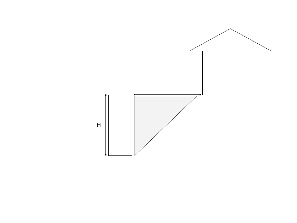
Taking the height of the retaining wall (from ground level) and measuring horizontally back from the top of the retaining wall, there is a zone of influence. This is represented by the ratio H1:1.
If a live or dead load falls within this zone then the design of the retaining wall needs to accommodate the load.
Tip: Tiered Retaining
A potential option for avoiding the consent process is to suggest a tier retaining wall configuration. Providing all rules are followed, this can be a cost effective and aesthetically pleasing solution.

The surcharge load should be specified by an Engineer prior to the commencement of the design process.
Simplification for reference below:
- 0 - 2.5 kPa load - garden/ landscaping walls;
- 5 kPa load - boundary walls in certain areas (e.g. Queenstown) unless specified otherwise;
- 12 kPa load - all cut boundary walls in certain areas if required by the local Council (e.g. Auckland Council), walls supporting driveway or pavement load;
- 24 kPa load - e.g when a house is closer than 1 x height of the wall to the wall.
Backfill Parametres
Backfill parameters & Base soil parameters
- Angle of friction (ɸ- degrees)
- Cohesion (c’ - kPa)
- Density (Y - kN/m3)
- Undrained bearing capacity (base soil only; SU- kPa)
- Subsoil classification (Class A, B, C, D & E)
The above parameters should be found in the geotechnical report as per the example snippets further in the manual (Geotech reports section). If the parameters have not been specified, additional geotechnical input may be required to confirm these.
Bearing Capacity of Soil
This is discussed at more length in the next section of this manual.
Profile of Wall
The configuration of Envirocon blocks and the subsequent profile of the wall can have positive impacts on the design.
The weight of the fill behind the wall can be utilised to provide additional overturning resistance. With Interbloc this means turning the base row perpendicular to the wall. With Stonebloc this means utilising the 800 or 1200 base block.
This approach can be applied to both gravity and cantilever walls.
When deciding on a trade off between adding extra blocks, which can increase costs for the customer, or increasing the length of the toe of the wall (i.e. using an 1800 instead of 1200 block for Interbloc, or 1200 instead of 800 block for Stonebloc) often increasing the length of the toe delivers a superior design outcome.
Tip: Backfill = 18 kN/m3 v Concrete 24 kN/m3.
Fall protection
It is a regulatory requirement that all walls with a fall of 1m or greater must have fall protection [balustrade] at the top of the wall. As a result the sales person will often need to take this into consideration.
There are three options for fall protection with Envirocon retaining walls:
- Top Fixed: the fence is fixed to the top of the wall.
- Rear Fixed: the fence is fixed to the back of the wall.
- Not Fixed: the fence is not fixed to the wall.
Fixing the fence to the wall creates a new surcharge - the potential live load of people pushing against the fence can be significant. This requires additional inputs to the design which create both benefits and negatives.
|
Benefits |
Negatives |
|
|
Top Fixed |
Maximises space utilisation Better aesthetic |
Requires stainless steel brackets to be added to the back of the wall to tie blocks together. |
|
Rear Fixed |
Cheaper than top fixing |
Slight loss of space Required to be fixed to multiple blocks |
|
Not Fixed |
Cheapest option Off the shelf designs |
Significant loss of useable space |
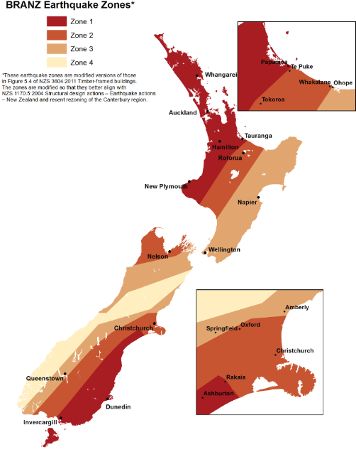
Earthquake
Affects the short-term sliding of the wall - the earthquake zone of the project can be verified using the map below. Zone 1- least risk & more liberal design; Zone 4- most risk & most conservative design.
Practical considerations:
Gravity wall designs in the Auckland and Northland (Zone 1) region may allow walls up to 2.4m high without additional need for vertical or horizontal (geogrid) reinforcing.
Gravity wall design in the Otago (Zone 3 & 4) region will make the retaining wall design more conservative and the maximum height of the wall utilising this approach lower. Specific engineering will often be required when the wall height exceeds 1.6/1.8m high.